Actuators are complete, mechatronic systems. They consist of a battery-free multi-turn rotary encoder, gears, a motor and integrated power and control electronics.
Actuators are intelligent adjustment units that can be attached to the end of a machine shaft or mounted onto a machine shaft or spindle. They convert incoming drive signals into mechanical rotary motion to drive the machine shaft. The mounting set (85000-51), consisting of a torque arm and mounting bracket, is used to prevent the drive from rotating with the machine shaft.
The actuators are not meant for continuous operation at nominal torque, but for short-time operation. The following intervals apply to the duty cycle (DC): At 100% load torque, the DC is 25%, which corresponds to a rated operating mode S2 with a base time of 4 minutes: duty cycle (DC) = 1 minute, followed by a pause duration (PD) of 3 minutes. With reduced load torque, the DC can be up to 50% depending on the ambient conditions and application. Other operating modes are protected by l2t and temperature monitoring and an adjustable current limiter. A briefly increased breakaway torque is permissible as part of this protection.
Material
Housing stainless steel or aluminium.
Adapter stainless steel.
Note
The actuators require two power supplies in the range 24 V to 30 V DC. The drives are equipped with a mechanical emergency manual override that enables manual operation in the event of a fault, e.g. a power failure. The drives can also be configured using the support tool via the service plug (mini-USB).
Assembly
The actuators can be mounted either with the narrow side horizontal or vertical to the machine shaft. In order to minimise the mechanical stress on all components, it is important that the output shaft (fixed bearing) and the attachment point of the torque support (floating bearing) are aligned. For horizontal installation, the actuators must be installed with the narrow side facing upwards. Installation in a transverse position, i.e. with the wide side facing upwards, is only permitted after careful assessment of the installation situation and subsequent approval by the manufacturer.
The mounting concept envisages a fixed/floating bearing arrangement. The fixed bearing supports the weight of the actuator by mounting the actuator directly onto the machine shaft via a hollow shaft with clamping ring. The torque arm prevents the actuator from rotating and acts as a floating bearing to compensate for any unbalanced movements on the output shaft.
On request
Software.
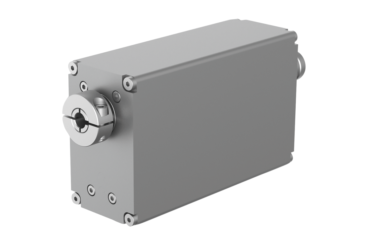
Drawing reference
1. Status display - device (LED1)
2. Status display - communication (LED2)
3. Communication interface (IN)
4. Communication interface (OUT)
5. Functional earth (M4 grub screw)
6. Removable blind plug for adjustment elements
7. Removable blind plug for manual adjustment
8. Power supply connector
9. Status display - IO-link status (LED1)
10. Status display - IO-link communication (LED2)
11. M12 connector: communication interface
12. M4 grub screw (functional earth)
13. Removable blind plug for adjustment elements
14. Removabe blind plug for service purposes
15. M12 connector: power supply
16. Horizontal mounting
17. Vertical mounting
18. Transverse position
19. Machine shaft
20. Plain bearing
21. Torque support
22. Shaft screw
Accessory
Mounting sets, stainless steel, for actuators 85000-51.
Connector for actuators 80150-30.