


Description
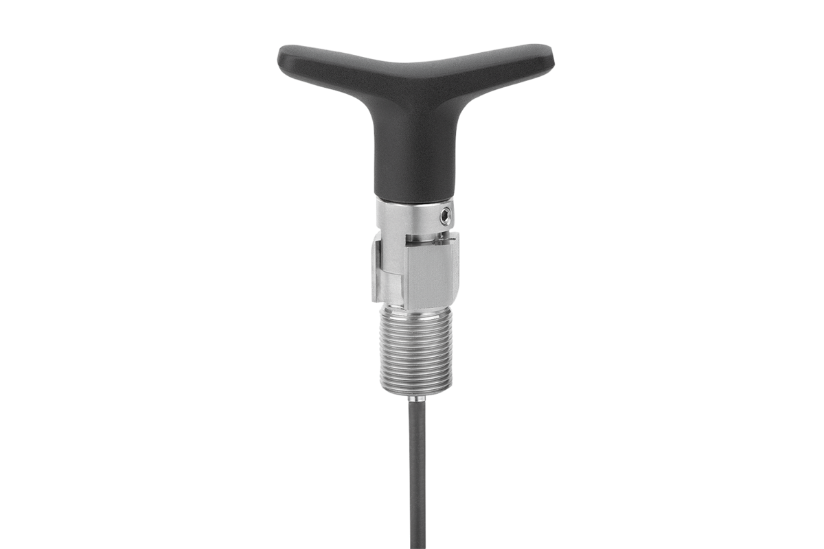
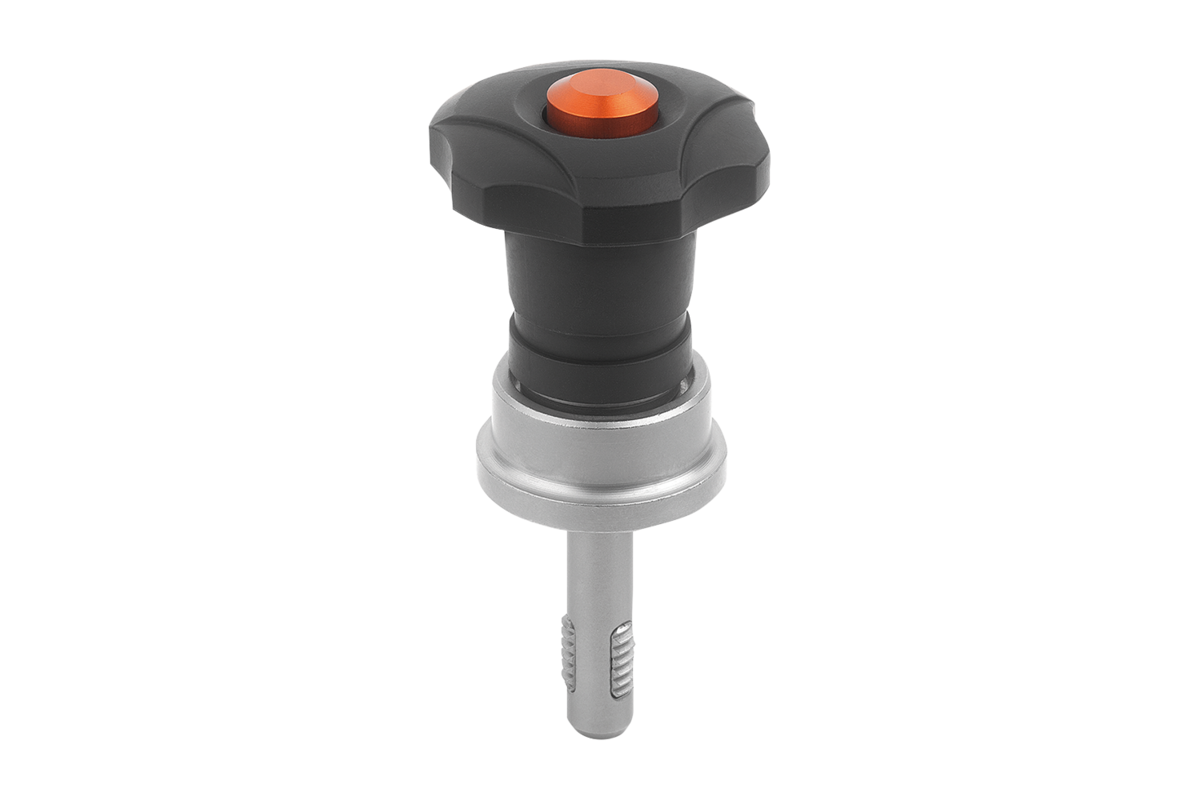
Threaded locking pins with an integrated clamping force intensifier can significantly increase the clamping force compared to standard threaded locking pins.
This product can also be used by people with limited manual strength (e.g. in the rehab sector), as it enables them to achieve equivalent clamping forces with little effort. Less manual force is also required to release the threaded locking pin.
When clamping, the retaining force is increased by the integrated axial bearing which creates very low surface friction on the fixed contact surface.
The large, fixed support surface always protects the clamped component.
Threaded locking pins are used for quick and easy fixating, connecting and clamping components.
The threaded segments can be unlocked by pressing the push button and the threaded locking pin can be inserted into or removed from a tapped hole. When the push button is released, the threaded segment engages securely.
Tightening torque max. 5 Nm.
The prerequisite for use is a precision tapped hole and corresponding material strength.
Corrosion protected.
Shear force double shear (F) = S · ? aB max.
The values given for the shear force are the theoretical breaking load.
These are non-binding reference values without consideration of safety factors and exclude any liability. The values given are for information purposes only and do not constitute a legally binding assurance of properties.
The load values have been calculated in accordance with DIN 50141.
The values apply to applications with inserted pin only (without applied torque).
Each user must determine individually whether the threaded locking pin is suitable for the respective application.
Different materials in which the threaded locking pins are used, weather conditions and wear can influence the determined values.
Technical specifications
Material
Pin in steel or stainless steel 1.4542.
Handle in thermoplastic.
Threaded element in stainless steel 1.4542.
Push-button in aluminium.
anti-friction bearing to increase clamping force in steel or stainless steel 1.4542.
Spring in stainless steel.
Finish
Pin in steel, treated and manganese phosphated.
Black handle.
Pin in stainless steel and precipitation-hardened threaded element.
anti-friction bearing to increase clamping force in nitrided and burnished steel.
Orange anodised push-button.
Temperature range
-30 °C up to +80 °C
Assembly
Assembly:
1. Press and hold the button.
2. Insert the threaded locking pin.
3. Release the button (the button must return to its initial position).
4. Tighten the threaded locking pin by hand as required.
5. Make sure the threaded segments are properly engaged in the housing thread.
Disassembly:
1. Unscrew the threaded locking pin by approx. a quarter turn counterclockwise.
2. Press and hold the button.
3. Remove the threaded locking pin.
4. Release the button.
| Brand | norelem |
|---|---|
| Category | Power transmission, Mechanical components |
| Subcategory | Actuators, Positioning System |